Contact Us

Procurement and project managers that are the ones specifying the gas detection equipment end up with a list of vendors, a range of products and absolutely no framework in which to define what a compliant installation actually has to be. The technical options are present, but without regulations managers choose based on price and brand alone. A flammable gas sensor selected outside that regulatory framework may pass initial procurement review and still fail the first AHJ inspection.
A compliant flammable gas sensor specification starts with the site’s hazardous location classification under NEC Article 500, works through the alarm setpoints that NFPA 30 and OSHA storage standards reference, and ends with an output configuration that integrates with the building’s existing suppression and ventilation infrastructure. Getting that framework in place before the purchase order is issued is what separates a compliant installation from a costly retrofit.
Procurement teams and EHS coordinators across the country rely on US Hazmat Rentals for flammable gas sensor systems configured to the site’s specific classification and integration requirements, delivered ready for installation and documentation before day one.
Lower Explosive Limit: the Standard Your Sensor Is Measured Against
A flammable gas sensor won’t detect all hazardous gases. It will only detect combustible gases and vapours within a certain concentration range (i.e. between the Lower Explosive Limit and the Upper Explosive Limit of the gas in question). Getting the sensor specified correctly starts with knowing what gas or vapours are actually present on site as not every sensor is suitable for every gas.
LEL is the minimum concentration of a gas in air at which it can ignite. Below the LEL the mixture is too lean to burn. Above the UEL it is too rich to burn. Within that range an ignition source will produce a fire or an explosion. Combustible gas detectors are designed to detect concentrations as a percentage of LEL rather than as parts per million (ppm) which allows a single calibration standard to be used for all gases.
Flammable examples of gases which will be the subject of gas detection installations are hydrogen (LEL 4%), methane (LEL 5%), propane (LEL 2.1%), acetylene (LEL 2.5%) and ethylene (LEL 2.7%). Any facility which stores petroleum distillates, has a battery charging area or deals with LPG at any stage of its process will have one or more of those gases as a potential leak.
Each is a flammable example that would fall within the detection range of a flammable gas sensor, though each would require the sensor to be calibrated to the particular gas LEL rather than to a generic hydrocarbon standard. Understanding Lower Explosive Limit in Gas Detection looks at the technical basis for LEL based detection and explains how the ISO 10156 and IEC 60079 values are used in the calibration of sensors.
Sensor Technologies and What Each Detects Best
Catalytic bead (pellistor) sensors work by oxidising the combustible gas on a heated element and measuring the temperature change. They are a very broad range of hydrocarbons, work perfectly well at the typical concentrations you’d find at a storage facility and are by far the most common type of sensor used for the detection of petroleum vapour and methane. The only real drawback is that high concentrations of silicone or lead compounds can permanently poison the sensing element.
IR optical sensors work by detecting combustible gases via light absorption at a wavelength specific to hydrocarbons. They are immune to poisoning and perform well in high CO2 environments so are the sensor of choice in an enclosed storage room or an area where the inert gas content is high. They don’t detect hydrogen (that requires a catalytic bead or electrochemical sensor).
Electrochemical sensors are the ones you go to if you need to identify a particular gas at low concentrations (catalytic bead sensors can be a bit lacking in resolution in that respect). PIDs measure VOCs down to sub-ppm levels and are used for spill and leak surveys rather than for continuous area monitoring.
The rules that apply to the installation of flammable gas sensors in a U.S. industrial plant come from two overlapping sets of regulations: NEC Article 500 which deals with the electrical classification of the area in which the sensor is situated, and the fire and storage codes (NFPA 30 and NFPA 72) which define the alarm parameters that the sensor must trigger.
NEC Article 500: Location Classification and Sensor Approval Requirements
NEC Article 500 (via NFPA 70) defines locations in terms of the nature and frequency of the presence of flammable gas or vapor. Class I, Division 1 locations are those in which flammable concentrations are present under normal operating conditions. Class I, Division 2 locations are those in which flammable concentrations are present only under abnormal or fault conditions.
The classification of the sensor’s mounting location determines the approval type the sensor must carry. In a Class I, Division 1 location, the sensor assembly must be either intrinsically safe or explosion-proof per the Division 1 approval. In a Division 2 location, the approval requirement is less stringent but still requires the sensor to be listed for Division 2 service.
Each flammable gas sensor deployed in a classified location should carry a UL 2075 listing (the standard for gas and vapor detectors), an FM approval, or an ATEX certificate when the facility is subject to international standards. The datasheet documentation confirming that listing must be part of the procurement package for AHJ review.
Alarm Setpoints and Why They Are Not Arbitrary
NFPA 30 requires that monitoring in hazardous liquid storage areas provide alarm output before the concentration in the space reaches 25% of LEL. The standard tier structure used across NFPA-compliant installations is a warning alarm at 10-25% of LEL, an action alarm at 50% of LEL, and a high-high alarm at 60-100% of LEL that initiates automatic shutdown or suppression activation. Each setpoint must be matched to the target gas’s LEL.
A flammable gas sensor programmed at the right alarm setpoints for its location classification does work before a hazard reaches action level. LEL Monitor Alarm Setpoints for Class 1 Div 1 Hazardous Areas details how setpoints differ between Division 1 and Division 2 classifications and identifies the NFPA 30 and NEC basis for each tier.
Sensor placement determines whether the detection system actually intercepts a developing hazard before it reaches the action threshold. The two placement variables that matter most are gas density relative to air and proximity to probable leak sources.
Placement by Gas Density
Heavier than air gases (propane, butane, LPG, most petroleum vapours) will tend to pool near the floor when released. Sensors for these gases should be located 12-18″ above floor level (in the vapour accumulation zone) rather than at the standard instrument height on a wall or column. Ceiling mounted sensors will not detect a propane release emanating from the floor until the concentration has already built up to a significant level.
Lighter than air gases (hydrogen, methane, natural gas) will rise towards the ceiling when released. For these gases sensors should be located within 12″ of the ceiling at the high point of the space as the stratification will see the ceiling concentration reach the alarm level before the floor level concentration does.
Identifying which of the categories the target gas falls into is a prerequisite to sensor placement, not something you work out after you’ve installed the sensor. If you end up with the wrong sensor in the wrong place then you’re back to square one with a full remount, re-cable and re-inspection. That’s all going to have a direct cost as well as a schedule impact.
Coverage Area and Number of Sensors
Standard industry guidance is that each flammable gas sensor is designed to cover an area of some 1500-2000 sq ft (this is reduced in areas of high air movement due to ventilation fans or HVAC). In the case of areas adjacent to potential leak points (fill and discharge ports, pipe fittings, valve packing etc) the sensor should be positioned within 10 feet of the source rather than just relying on the general area coverage.
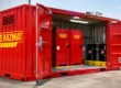
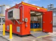
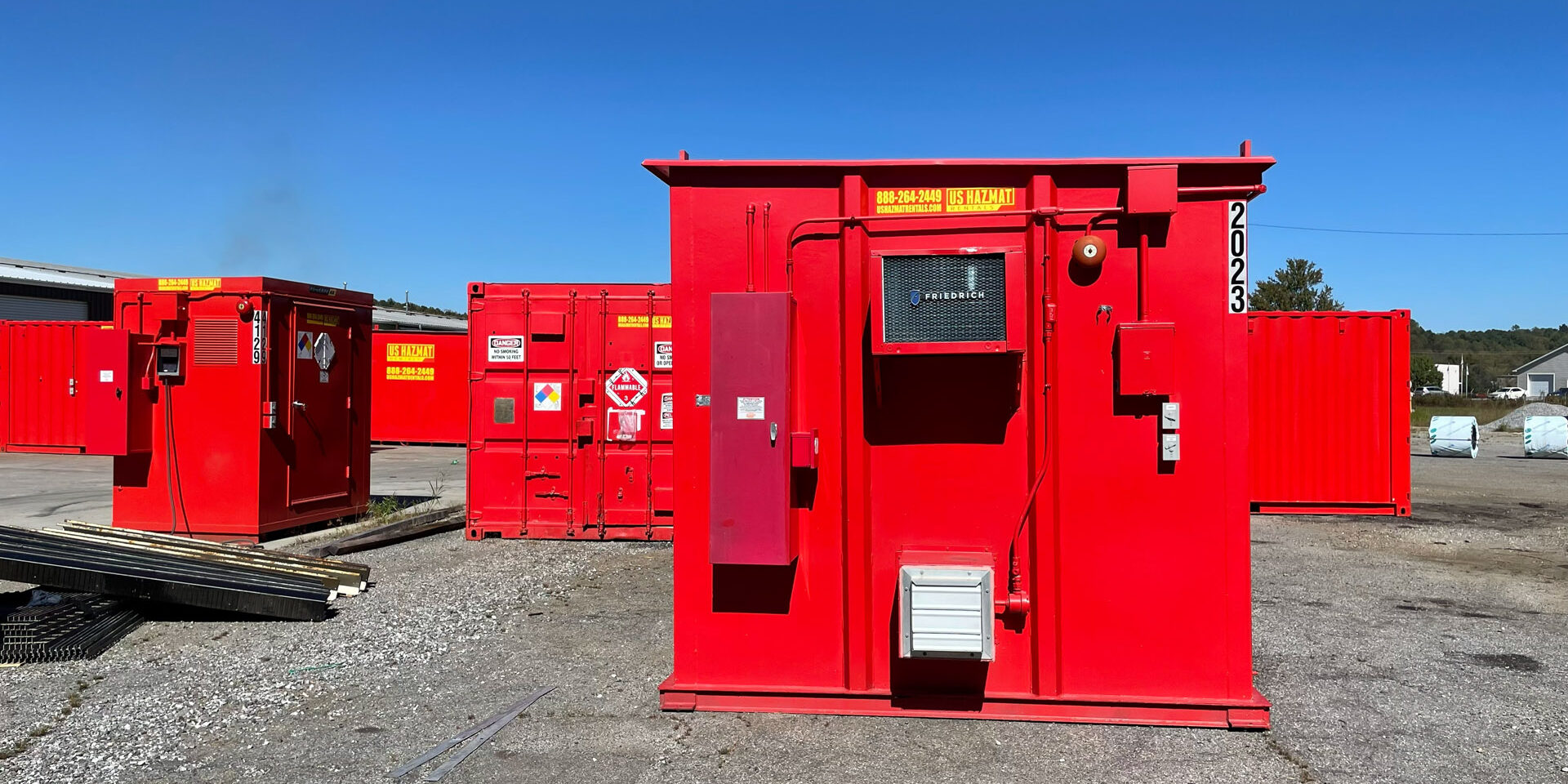
US Hazmat Rentals have the gas sensor placement and coverage right into the storage building specification from the outset. The number of sensors, the cable routing and the control panel integration are all part of the building package rather than something that’s added on. Explore the full flammable storage protection options and confirm the building configuration that fits your site’s gas profile and coverage area.
Fire Suppression Trigger and Automated Response
A standalone sensor unit which will annunciate locally but doesn’t connect to a building control system will satisfy the detection requirement but will not close the loop in response. NFPA 30 and the interpretation of most AHJs would require that gas detection in hazardous liquid storage areas be linked into a response sequence which would be activated prior to personnel being expected to respond manually to the alarm.
Sensor output configuration dictates which building system will respond to an alarm. A 4-20mA analogue output will produce a proportional signal to a control panel which can then be programmed to respond in a staged manner by setpoint. A relay output will trigger a fixed response (a ventilation fan start, suppression system activation or an electrical shutdown being the most common) when the alarm threshold is exceeded.
The most typical automated response sequence for a Class I storage room is: 10-25% LEL will trigger forced ventilation to start; 50% LEL will trigger the alarm and automatic shutdown of all non-essential electrical loads; 60% or above will trigger the fire suppression system (if present). The building systems for flammable liquid vapours and those for the safe storage of lithium ion batteries are both based on the same LEL logic.
US Hazmat Rentals integrates fire suppression systems with gas sensor output as part of the storage building specification, so the sensor, control panel, and suppression trigger are pre-wired and tested before the unit arrives on site. Contact the team to confirm whether your site’s output configuration requirements align with the available building packages.
Procurement Checklist for a Flammable Gas Sensor Specification
Five items must appear in every specification package for gas detection equipment submitted for AHJ review:
Target gas and calibration standard: name the specific gas or vapor. The sensor must be calibrated to that gas’s LEL, not to a generic methane-equivalent standard, unless the target gas is methane.
Location classification: identify the Division 1 or Division 2 classification of the mounting location under NEC Article 500. The classification drives the approval type requirement.
Approval listing: confirm UL 2075, FM, or ATEX approval at the matching Division. Include the approval certificate and listing number in the procurement package.
Output type: specify 4-20mA, relay, or Modbus RTU/RS-485 based on the control panel or building automation system the sensor will connect to. Mismatched output types are a frequent cause of re-procurement after delivery.
Calibration and maintenance documentation: specify the calibration interval (typically 3-6 months for catalytic bead sensors, 6-12 months for IR sensors), identify the calibration gas source, and confirm a maintenance log template is included in the package. Calibration records must be available for every AHJ inspection after installation.
Get Your Flammable Gas Sensor Specification Right Before Purchase
A flammable gas sensor selected against a compliance framework of location classification, target gas, approval listing, alarm setpoints, and output integration delivers both regulatory coverage and operational confidence. One selected outside that framework typically delivers neither. The compliance gaps surface during the first AHJ inspection or during the first calibration check, at which point the cost to correct them exceeds the cost to specify correctly from the start.
US Hazmat Rentals works with procurement teams and project managers across the country to configure flammable gas sensor systems for facilities storing Class 3 flammable liquids, compressed gases, and other hazardous materials. Contact our team today to get a custom proposal for your facility.
FAQ
What is a flammable gas sensor and what does it detect?
A flammable gas sensor detects combustible gases and vapors within the concentration range between their Lower Explosive Limit (LEL) and Upper Explosive Limit (UEL) in air. It outputs a signal proportional to the concentration as a percentage of LEL, which can trigger alarms, ventilation, or suppression responses at defined thresholds. Common target gases include methane, propane, hydrogen, acetylene, and petroleum vapors.
What approvals are required for a flammable gas sensor in a classified location?
In NEC Class I, Division 1 locations, a flammable gas sensor must carry an intrinsically safe or explosion-proof approval (UL 2075, FM, or ATEX) for Division 1 service. In Division 2 locations, a Division 2 listing is required. The approval certificate must be available for AHJ review as part of the installation documentation package.
Where should a flammable gas sensor be mounted?
Heavier-than-air gases (propane, LPG, petroleum vapors) require sensors mounted 12-18 inches above floor level. Lighter-than-air gases (hydrogen, methane) require sensors mounted within 12 inches of the ceiling. Standard wall-height installation does not satisfy either requirement and will delay detection in both scenarios.
What alarm setpoints should a flammable gas sensor be programmed to?
For facilities governed by NFPA 30, the standard tier structure is 10-25% LEL for a warning alarm, 50% LEL for an action alarm that initiates ventilation or facility response, and 60-100% LEL for a high-high alarm that activates automatic shutdown or fire suppression. Each setpoint should be calibrated to the target gas’s LEL rather than a generic default.
How often does a flammable gas sensor need to be calibrated?
Catalytic bead sensors typically require calibration every 3-6 months. Infrared optical sensors are typically calibrated every 6-12 months. The calibration interval should be documented in the maintenance plan, and the calibration gas source must be identified in the procurement specification. Calibration records must be available for AHJ inspections.